Show Temperature and Humidity as WiFi SSID with ESP8266 and HTU21D Sensor

Since I started playing with ESP8266 WiFi microcontroller in 2016, I had a TMP36 temperature sensor. TMP36 is an analog sensor: it uses a voltage between 0.00V and 1.75V to represent a temperature reading between -50℃ and 125℃. The ESP8266 has an analog-to-digital converter (ADC) capable of reading voltages up to 1.00V. To read a temperature from TMP36 into ESP8266, I need to use a pair of resistors as a voltage divider, so that the resulting voltage does not exceed ADC's limit. However, I feel the temperature reading is very inaccurate: is my room really 19℃ when @TheTucsonHeat is in town? I once replaced the carbon resistors with metal film resistors, and the temperature reading instantly changed by as much as 8℃.

I need an upgrade to the temperature sensor! The new sensor must output digital signal, so that my lousy resistors wouldn't affect its accuracy. After comparing DHT11, DHT22, DS18B20, and several others, I eventually chose HTU21D-F because it has an I2C interface, which can be added directly to my LCD kit.

The HTU21D sensor arrives in the mail a few weeks later. It needs a bit of soldering to add the pin headers onto the breakout board; ImmodderNation has a soldering video to get you started. Afterwards, wiring is simple: just add it into the existing I2C bus! As long as you don't short the wires, you won't burn down the office.

HTU21D on I2C bus of ESP8266

A quick test with Adafruit's library confirms the HTU21D sensor is working correctly. Temperature and humidity readings are showing up on the serial console. However, I don't want to tug around the laptop to measure temperature around the house, and don't want to program the LCD or connect to Losant or NDN right away. I thought up a quick and easy way: let's create a Wi-Fi hotspot from the ESP8266, and show temperature and humidity as the WiFi network name (SSID)!
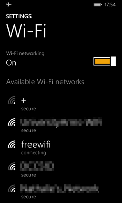
"freewifi" via ESP8266 Captive Portal

Many outdoor places do not have permanent Wi-Fi access points. Occasionally I can get a weak unencrypted WiFi signal from a nearby shop; otherwise, I'll have to face the fact of not having WiFi, and resort to my slow and expensive SIM card for cellular Internet access.

Since I learned that the ESP8266 can serve as a WiFi hotspot, I got an idea. I can make an ESP8266 appear as a Wi-Fi access point (AP), and provide free WiFi to everyone at the outdoor venue. Except that, this is a freewifi prank: I am providing free WiFi, but my WiFi does not offer Internet access.

Screenshots

ESP8266 makes a freewifi WiFi access point SSID:

freewifi SSID

ndnping Jewelry on ESP8266

I was wearing a unique piece of jewelry at NDN community meeting, Mar 2017: a pair of ESP8266 units that communicate with each other over the NDN testbed. They are ugly, but it is a nice way to demonstrate my creation in a Named Data Networking community meeting.

Two Witty Cloud boards are tied to my wrists, and powered by a USB powerbank in my pocket. One of them runs a ndnping client, and the other runs a ndnping server. The client sends Interests to a router in Arizona, the Interests (under a multicast prefix) are flooded through the testbed, and reach the server which is connected to a router in Memphis.

Arduino Code

Library: esp8266ndn

Count-Up Timer on ESP8266 and I2C LCD

I need a count-up timer on the desk so that I can do a presentation without turning my head to the wall clock. So I wrote one with ESP8266 and I2C-connected LCD unit.

photo of LCD count-up timer using ESP8266

#include <LiquidCrystal_I2C.h>

LiquidCrystal_I2C lcd(0x3F, 16, 2);

void
setup()
{
  lcd.begin(16, 2);
  lcd.init();
  lcd.backlight();
}

void
loop()
{
  int seconds = millis() / 1000;
  int minutes = seconds / 60;
  seconds %= 60;

  lcd.clear();
  lcd.print(minutes);
  lcd.print(':');
  if (seconds < 10) {
    lcd.print('0');
  }
  lcd.print(seconds);
  delay(100);
}

Hardware is Losant LCD Kit. I'm using Marco Schwartz's LiquidCrystal_I2C library.

Access C.H.I.P UART Wirelessly with ESP8266

A year ago, a Kickstarter campaign CHIP - The World's First Nine Dollar Computer caught my attention: it's a $9 computer smaller than a banana. Unlike the Raspberry Pi, it comes with onboard storage so I don't need to buy a separate SD card, it has WiFi instead of wired Ethernet so I don't have to run wires everywhere, and it is compatible with my existing VGA monitor through a $10 adaptor so I don't have to buy another HDMI monitor. Therefore, I snagged two of these little computers along with one VGA adapter during the campaign.

During the whole year of waiting, Next Thing Co sent me regular email updates on the development progress, with each email ending with mmmtc (much much more to come) and a lot of hearts. NTC also clarified that C.H.I.P is strictly B.Y.O.B. Finally, my pair of CHIPs and a VGA DIP arrived in my mailbox on Jun 16. An hour later, yoursunny.com homepage is displayed on its Debian desktop.

A few more hours later, I start to discover a limitation of C.H.I.P software: The Linux kernel comes with CHIP operating system has very limited features.

$ sudo modprobe fuse
modprobe: FATAL: Module fuse not found.

Obviously, the solution to this problem is to compile my own Linux kernel with more features. The compilation can be done on the C.H.I.P itself. I managed to do that when the CHIP is powered by a 5V 1A phone charger plus a 1500mAh LiPo battery. I had the compilation running under screen(1) and attended to it intermittently, and it finished in a day.

Do Evil with ESP8266: Slow Down the WiFi

While hackers do good most of the time, we occasionally do evil and play a prank. The ESP8266, unlike JSON, allows me to do evil. Thus, I programmed the microcontroller for an evil purpose: slow down the WiFi.

How it Works

802.11 WiFi typically operates in infrastructure mode, where a router acts as an access point, and other hosts (stations) connect to the router on a wireless frequency (a channel).

One property of the wireless channel is that, at any moment, only one party (station or access point) can be transmitting. If multiple senders are transmitting at the same time, the wireless signal will be jammed, and the recipient is unlikely to receive the packet correctly. In this case, the sender would have to transmit the packet again at a later time.

Packets can be transmitted at different speeds on the wireless channel. With 802.11g standard, the maximum speed is 54Mbps, and the minimum is as slow as 1Mbps. The sender (station or access point) dynamically chooses a speed for every packet depending on its perception of wireless channel quality. Usually, we prefer to transmit at a higher speed, so that the wireless channel can be freed as soon as possible for other senders to use. However, if the sender and recipient are far apart, high speed transmission is less likely to succeed because signals can be faded, and a slower speed is necessary to increase the chance of a successful transmission.

Flash ESP8266 Witty Cloud Board with 6 Wires

Witty Cloud board is an ESP8266 development board that has a unique two-PCB design: the top PCB carries the ESP8266 microcontroller and an AMS1117 voltage regulator, and the bottom PCB carries a CH340G USB-serial chip. The top PCB can operate independently. It has a pair of 8-pin male headers that expose ESP8266's GPIO pins, which can be used to control peripherals such as LEDs and buttons. The bottom PCB is needed only for flashing the ESP8266. It has a pair of 8-pin female headers. The top PCB should be inserted into the bottom PCB when the firmware is being flashed from a computer, or when we want to use Arduino's serial monitor.

Sometimes, we may want to simultaneously connect ESP8266's GPIO pins to peripherals, and keep the ability of flashing the firmware or monitoring the serial console from a computer. Can we achieve that?

From electric point of view, when the male headers on the top PCB are inserted into the female headers on the bottom PCB, each of the 16 pins on one PCB is connected to the corresponding pin on the other PCB via a wire. Thus, if we connect the two PCBs with 16 jumper wires, everything should work.

But it's tedious to connect 16 wires every time. Can we connect the two PCBs with less jumper wires? Let me find out.

I started with four wires:

Understanding the Photoresistor on Witty Cloud Board

One of my favorite electronic elements is the photoresistor, an element whose resistance decreases with increasing incident light intensity. I played with a photoresistor as part of an electronic building blocks toy kit when I was in elementary school, and made a geocaching trackable out of that experience. But I want a deeper understanding of the photoresitor: what's the correlation between its conductivity and the light intensity?

photoresistor circuit symbol

Recently I acquired some Witty Cloud boards. This board is built around an ESP8266 microcontroller; a photoresistor (aka Light Dependent Resistor, LDR) is connected to the analog input port of the ESP8266. With one line of code in Arduino (analogRead(A0)), we could read the light intensity as a number between 0 and 1023. However, what's the unit of this number, and how does it translate to the standard units such as lumens?

I couldn't find any formula for this translation, because it does not exist. Adafruit explains photoresistor readings nicely:

The readings taken are not in any useful units of light intensity. Photoresistors are not carefully calibrated sensors. If you wanted to make a light meter, with absolute measurement of light intensity in meaningful units, you would need to create a lookup table that related readings with readings taken from a properly calibrated light meter.

First Impression on ESP8266 Witty Cloud Board

I get addicted to ESP8266 ever since Losant sent me a builder kit which includes an Adafruit Feather HUZZAH. Witty Cloud GitWits is one of the cheapest ESP8266 device you can get on the market. It has a microUSB port with USB-Serial interface, which means no soldering! The board also contains an RGB LED and a button, which allows me to use it without a breadboard. So, I decide to go for it!

I ordered the Witty Cloud board from AliExpress, a Chinese E-commerce site. Ordering experience isn't so good. For some reason, they cancelled my order due to "difficulty in verifying payment". I had to upload a scanned copy of my passport and credit card statement, before they would ship my items. After getting past those non-technical steps, the Witty Cloud development board is in my mailbox 2 weeks later. There's no doubt I'm excited!

Appearance

The board is very small and lightweight. Its dimension is 31mm x 30mm x 18mm. Its weight is roughly the same as an Adafruit Feather HUZZAH.

Witty Cloud board has two PCBs connected via a pair of 8-pin headers.

LosantPingPong: End-to-end Losant Connectivity Test

Losant is a simple and powerful IoT cloud platform. The platform provides a MQTT broker that sensor devices can connect to and report state in real time; the reported states are stored in the cloud, and can be visualized in several formats.

Recently, Losant sent me a Builder Kit which contains an ESP8266 WiFi chip on Adafruit Feather Huzzah, a TMP36 temperature sensor, and some other components. Following the official instructions, 1.5 hours later, my room temperature shows up on a webpage.

I'm excited, and I decide to leave it running continuously so that I can monitor the activities of @TheTucsonHeat. However, Losant platform shows the device as "offline" from time to time, and sometimes it never comes back online unless I press the hard-reset button. This is mostly because of the bad WiFi in my apartment: 1000ms huge delay, 10% or more packet loss, etc. Since MQTT is based on TCP, it's severely affected. To make things worse, our WiFi connects to the Internet through two levels of Network Address Translation (NAT) gateways; it seems that the ESP8266 sometimes is unable to detect the TCP connection to Losant broker is broken, and thus does not take recovery actions.

As a computer networking student, the first thing coming through my mind is the end-to-end principle: the reliability of an application should be ensured by the end hosts, not by the network. To test whether my temperature sensor remains connected to Losant, I should send a message to the Losant platform, and let the platform send back a reply. And that's the idea of LosantPingPong: an end-to-end connectivity test between a connected device and the Losant platform.

LosantPingPong protocol