I get addicted to ESP8266 ever since Losant sent me a builder kit which includes an Adafruit Feather HUZZAH. Witty Cloud GitWits is one of the cheapest ESP8266 device you can get on the market. It has a microUSB port with USB-Serial interface, which means no soldering! The board also contains an RGB LED and a button, which allows me to use it without a breadboard. So, I decide to go for it!
I ordered the Witty Cloud board from AliExpress, a Chinese E-commerce site. Ordering experience isn't so good. For some reason, they cancelled my order due to "difficulty in verifying payment". I had to upload a scanned copy of my passport and credit card statement, before they would ship my items. After getting past those non-technical steps, the Witty Cloud development board is in my mailbox 2 weeks later. There's no doubt I'm excited!
Appearance
The board is very small and lightweight. Its dimension is 31mm x 30mm x 18mm. Its weight is roughly the same as an Adafruit Feather HUZZAH.
Witty Cloud board has two PCBs connected via a pair of 8-pin headers.
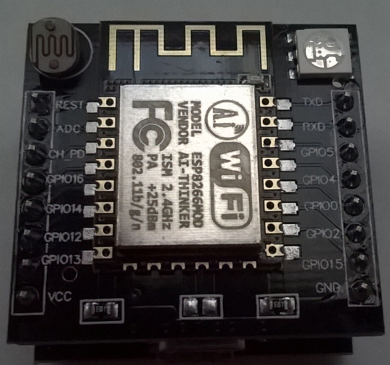
Top PCB has our main player, an ESP8266MOD WiFi microcontroller. There is a photoresistor on the top-left corner, and an RGB LED on the top-right corner.

Back side of top PCB has two rows of male headers for connection to the bottom PCB. An AMS1117 voltage regulator sits in the center, which is responsible for supplying 3.3V power to the ESP8266. There is a button on the top edge, and a micro USB port on the bottom edge.
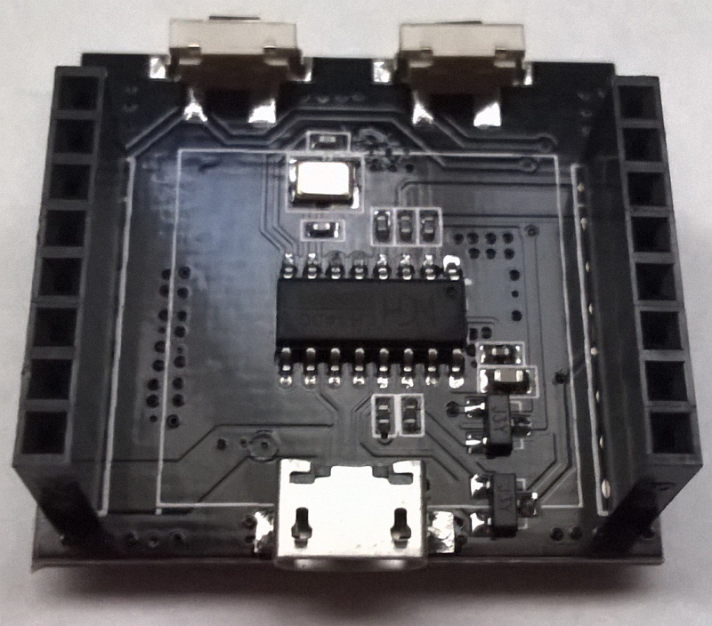
Bottom PCB has two rows of female headers where the top PCB can be inserted into. A CH340G USB-Serial chip sits in the center, so that my computer could talk to the ESP8266. A little 12.000MHz crystal assists the CH340G to do its job. There are two buttons on the top edge, and a micro USB port on the bottom edge.

Back side of bottom PCB has nothing on it, because it's the very bottom of an assembled board.
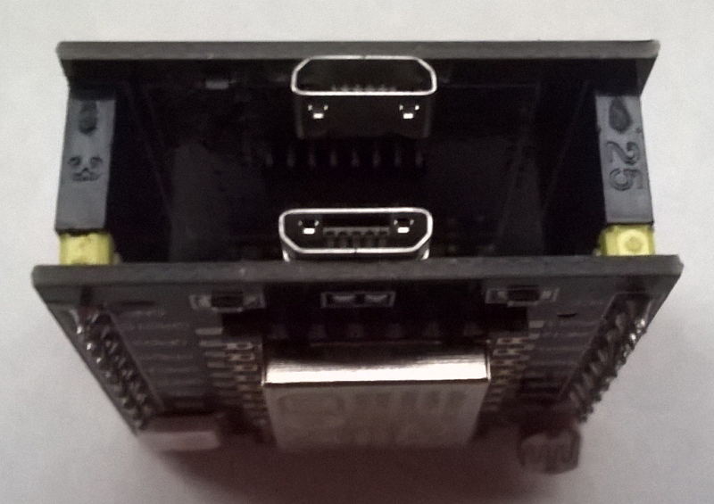
When assembled, we can see two micro USB ports on one side, and three buttons on the other side.

It's said that this design allows the top PCB to be deployed alone, while the bottom PCB is connected only when the ESP8266 needs to be re-programmed.
Plug it in!
As soon as I connect the board to my computer with a micro USB cable, the green LED turns on, and a tiny blue LED (next to the WiFi antenna) blinks once.
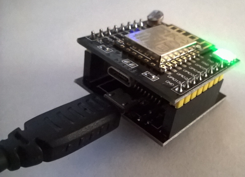
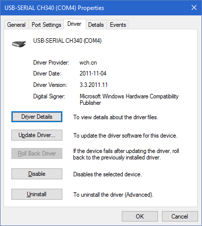
Windows 10 did a nice job and recognizes CH340G USB-Serial chip automatically. No driver download is necessary.
Simple Blink Program
Witty Cloud, being an ESP8266 chip, can be programmed with Arduino IDE.
Programming environment is same as Adafruit Feather HUZZAH, so I just followed Losant IoT Developer Kit Environment Setup procedure (except that CP2102 driver is unnecessary because our board uses CH340G).
The Streaming.h library can be downloaded as a ZIP.
I have tried a simple program that blinks every GPIO pin.
#include <Streaming.h>

void setup() {
  Serial.begin(115200);
  Serial.println();
  Serial.println();

  Serial << "setup\n";
}

void blink(int pin) {
  Serial << "analogRead(A0)=" << analogRead(A0) << "\n";

  pinMode(pin, OUTPUT);
  Serial << "pinMode(" << pin << ",OUTPUT)\n";
  delay(1000);

  digitalWrite(pin, 0);
  Serial << "digitalWrite(" << pin << ",0)\n";
  delay(1000);

  digitalWrite(pin, 1);
  Serial << "digitalWrite(" << pin << ",1)\n";
  delay(1000);

  for (int pct = 10; pct <= 90; pct += 10) {
    analogWrite(pin, static_cast<int>(PWMRANGE * 0.01 * pct));
    Serial << "analogWrite(" << pin << "," << pct << "%)\n";
    delay(1000);
  }

  analogWrite(pin, 0);
}

void loop() {
  blink(0);
  blink(2);
  blink(4);
  blink(5);
  blink(12);
  blink(13);
  blink(14);
  blink(15);
  blink(16);
}
The available GPIO pin numbers are same as the GPIO pins of Adafruit Feather HUZZAH: #0, #2, #4, #5, #12, #13, #14, #15, #16. All these GPIO pins are accessible on the male headers of the top PCB. Other pin numbers, such as #1 or #3, cannot be used. When I attempt to "blink" them, the microcontroller would reset itself.
I recorded a video showing the effect of this blink program. It indicates that the pinout of this board is:
- GPIO#2 controls the tiny blue LED next to the WiFi antenna. HIGH turns off the LED, and LOW turns on the LED.
- GPIO#15 controls red of the RGB LED. HIGH turns on the color, and LOW turns off the color.
- GPIO#12 controls green of the RGB LED. HIGH turns on the color, and LOW turns off the color.
- GPIO#13 controls blue of the RGB LED. HIGH turns on the color, and LOW turns off the color.
Unlike what other people have found, all four GPIO pins support PWM.
That's what I found during my first two hours with the Witty Cloud development board. I can't wait to explore more.