One of my favorite electronic elements is the photoresistor, an element whose resistance decreases with increasing incident light intensity. I played with a photoresistor as part of an electronic building blocks toy kit when I was in elementary school, and made a geocaching trackable out of that experience. But I want a deeper understanding of the photoresitor: what's the correlation between its conductivity and the light intensity?

Recently I acquired some Witty Cloud boards.
This board is built around an ESP8266 microcontroller; a photoresistor (aka Light Dependent Resistor, LDR) is connected to the analog input port of the ESP8266.
With one line of code in Arduino (analogRead(A0)), we could read the light intensity as a number between 0 and 1023.
However, what's the unit of this number, and how does it translate to the standard units such as lumens?
I couldn't find any formula for this translation, because it does not exist. Adafruit explains photoresistor readings nicely:
The readings taken are not in any useful units of light intensity. Photoresistors are not carefully calibrated sensors. If you wanted to make a light meter, with absolute measurement of light intensity in meaningful units, you would need to create a lookup table that related readings with readings taken from a properly calibrated light meter.
But at least, I could have an impression on how the photoresistor react to different light intensities.
Instant Readings
Using the Arduino environment setup previously, I wrote a simple program that reads the photoresistor on analog input repeatedly.
void setup() {
  Serial.begin(115200);
  Serial.println();
}

void loop() {
  Serial.print(millis());
  Serial.print(" ");
  Serial.println(analogRead(A0));
  delay(100);
}
I programmed two Witty Cloud boards, and then exposed the photoresistor to different lighting conditions. Here's the readings from two boards:
| condition | reading-A | reading-B |
|---|---|---|
| inside a closed drawer | 0 | 1 |
| laptop screen black area, lowest brightness setting | 17 | 19~21 |
| laptop screen white area, lowest brightness setting | 60~80 | 70~110 |
| laptop screen black area, highest brightness setting | 62 | 80 |
| laptop screen white area, highest brightness setting | 413 | 464 |
| white paper illuminated by white LED lights | 1024 | 1024 |
| wood desk illuminated by white LED lights | 780 | 665 |
| white paper illuminated by desk lamp with incandescent bulb | 760~800 | 775~790 |
| brown carpet illuminated by desk lamp with incandescent bulb | 372~382 | 375~400 |
There's quite a difference between these two boards. This means, if I want to convert the readings to lumens, I would have to calibrate each device separately. However, the two boards have the same general trend: the readings get larger with higher light intensity. Thus, without calibration, the photoresistors can detect whether it's day or night, or whether I forget to turn off a lamp.
Determine the Range of Day and Night
To determine whether it's day or night based on light intensity, we need to find out what values would the photoresistor read in different times of the day. This needs a whole day of experiment. It would be boring to stare at Arduino's serial monitor for 24 hours straight. Luckily, our friends over at Losantiville, OH can help: I can let the Witty Cloud boards report its photoresistor readings periodically to the Losant IoT platform, and then let the platform plot the readings.
Arduino program
The program is a simplified version of Losant Builder Kit workshop 3:
#include <ESP8266WiFi.h>
#include <Losant.h>

const char* WIFI_SSID = "my-wifi-ssid";
const char* WIFI_PASS = "my-wifi-pass";
const char* LOSANT_DEVICE_ID = "my-device-id";
const char* LOSANT_ACCESS_KEY = "my-access-key";
const char* LOSANT_ACCESS_SECRET = "my-access-secret";

WiFiClientSecure wifiClient;
LosantDevice device(LOSANT_DEVICE_ID);

void connect() {
  unsigned long connectionStart = millis();
  while (WiFi.status() != WL_CONNECTED) {
    delay(100);
    WiFi.begin(WIFI_SSID, WIFI_PASS);
    if (millis() - connectionStart > 30000) {
      ESP.restart();
    }
  }

  device.connectSecure(wifiClient, LOSANT_ACCESS_KEY, LOSANT_ACCESS_SECRET);
  connectionStart = millis();
  while (!device.connected()) {
    delay(100);
    if (millis() - connectionStart > 30000) {
      ESP.restart();
    }
  }
}

void setup() {
  pinMode(2, OUTPUT);
  digitalWrite(2, HIGH);
  pinMode(15, OUTPUT);
  digitalWrite(15, LOW);
  pinMode(12, OUTPUT);
  digitalWrite(12, LOW);
  pinMode(13, OUTPUT);
  digitalWrite(13, LOW);
}

void reportReading(double reading) {
  StaticJsonBuffer<200> jsonBuffer;
  JsonObject& root = jsonBuffer.createObject();
  root["reading"] = reading;
  device.sendState(root);
}

unsigned long lastReport = 0;
long readingTotal = 0;
int nReadings = 0;

void loop() {
  if (WiFi.status() != WL_CONNECTED || !device.connected()) {
    connect();
  }
  device.loop();

  readingTotal += analogRead(A0);
  ++nReadings;

  if (millis() - lastReport > 15000) {
    double avg = static_cast<double>(readingTotal) / nReadings;
    reportReading(avg);

    lastReport = millis();
    readingTotal = 0;
    nReadings = 0;
  }

  delay(100);
}
The setup() function ensures all LEDs on the board are turned off, so that they don't emit light at night and interfere with the readings.
In loop() function, every 15 seconds, the program calculates the average photoresistor reading since the last report, and send it to the Losant IoT platform.
Losant platform configuration
Losant platform needs to be configured to accept and store those reports.
Since I have two devices, it makes sense to use Losant's "device recipe" feature.
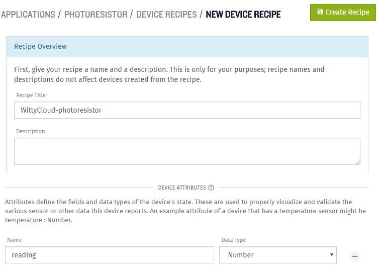
First, I create a device recipe with a "reading" attribute of Number type:
Then, I use this recipe to create devices:

The two devices I have are simply named "A" and "B":

Access key configuration is same as any other Losant workshops. The two devices can share the same access key, but they must be programmed with different device IDs in order to connect successfully.
Device deployment
A pint of delicious blueberries later, the blueberry box becomes a container for two Witty Cloud boards.
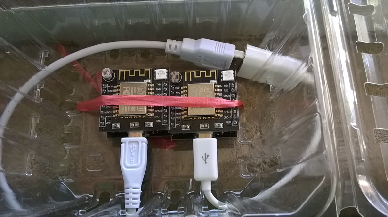
Since each board has two micro USB ports, I could use just one phone charger to run both boards. A phone charger rated at 1000mA supplies power to the lower USB port on the left board; an OTG cable and a regular micro USB cable connects together upper USB ports of both boards, so they both get power. This method should not overheat the AMS1117 voltage regulator, because power pins of two micro USB ports on the same board are connected together directly through VCC and GND pins on the headers, and they don't go through the AMS1117.
The result
1 day later, it's time to see the results!
The results are plotted with a "time series graph" on a Losant dashboard, configured as:

The red curve shows the readings from device "A"; the blue curve shows the readings from device "B".
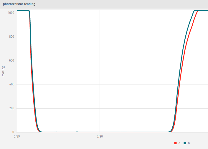
We can see that, while the two boards have slightly different readings, they both read near the maximum during the day, and near the minimum at night. To be exact, the daytime reading is almost always "1020", and the night time reading is between 0 and 2. Therefore, for the purpose of determining whether it's day or night, any value in the middle, such as "512", could be used as a cut-off.
I also take a closer look at the readings during sunset and sunrise.
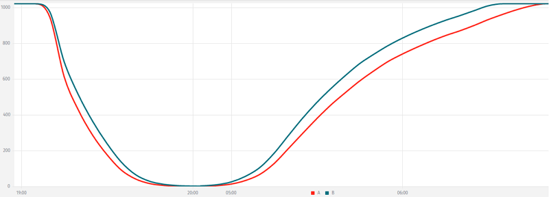
Sunset on May 29, 2016 in Tucson, AZ was 19:24. However, we can see the readings begin to drop at 19:10, and it reaches the "night time" range around 20:00. Sunrise on May 30, 2016 in Tucson, AZ was 05:18. Similarly, the readings begins to rise at 04:50, and it reaches the "daytime" range around 06:40. Coincidentally, civil twilight ends at 19:52 on May 29 and starts at 04:50 on May 30. Thus, civil twilight is detectable by the photoresistors.
With these experiences, I should be more knowledgeable about the ESP8266 Witty Cloud board, and its onboard photoresistor (Light Dependent Resistor, LDR) in particular.