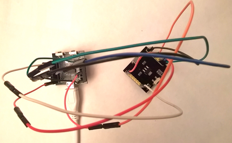
Witty Cloud board is an ESP8266 development board that has a unique two-PCB design: the top PCB carries the ESP8266 microcontroller and an AMS1117 voltage regulator, and the bottom PCB carries a CH340G USB-serial chip. The top PCB can operate independently. It has a pair of 8-pin male headers that expose ESP8266's GPIO pins, which can be used to control peripherals such as LEDs and buttons. The bottom PCB is needed only for flashing the ESP8266. It has a pair of 8-pin female headers. The top PCB should be inserted into the bottom PCB when the firmware is being flashed from a computer, or when we want to use Arduino's serial monitor.
Sometimes, we may want to simultaneously connect ESP8266's GPIO pins to peripherals, and keep the ability of flashing the firmware or monitoring the serial console from a computer. Can we achieve that?
From electric point of view, when the male headers on the top PCB are inserted into the female headers on the bottom PCB, each of the 16 pins on one PCB is connected to the corresponding pin on the other PCB via a wire. Thus, if we connect the two PCBs with 16 jumper wires, everything should work.
But it's tedious to connect 16 wires every time. Can we connect the two PCBs with less jumper wires? Let me find out.
I started with four wires:
- GND: ground of power supply and signals
- VCC: supply 5V power from bottom PCB's micro USB port to the AMS1117
- RX: signal from computer to ESP8266
- TX: signal from ESP8266 to computer
But this doesn't work. Arduino cannot flash the firmware.
Then I recall that to put the ESP8266 into flash programming mode, it needs to reset while holding its GPIO0 pin low. Thus, I added two more wires:
- REST: reset signal
- GPIO0: flash programming mode selection signal
And it worked! Under this configuration, I can not only flash a firmware into the ESP8266 on the Witty Cloud board, but also use Arduino's serial monitor to debug the firmware with peripherals.

Caution: Make sure two PCBs are oriented in the same direction (e.g. micro USB ports on the left); VCC is 5V, so if you connect it to the wrong pin, bye-bye ESP8266. The top PCB does not fit on a regular breadboard so I'm using two breadboards; make sure two breadboards are on a flat surface, otherwise the male headers on the top PCB may be bent.
If you are ambitious or just don't want to use two breadboards, it's also possible to connect them with 6 dupont wires.
